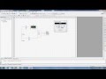
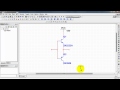
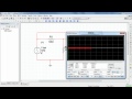
This video describes the basics of using National Instruments MultiSim Circuit Design and Simulation software. The simulation is a basic series circuit and measurements are performed using virtual test equipment. This video is intended as an introduction
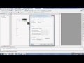
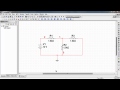
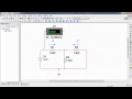
This video describes the basics of using National Instruments MultiSim Circuit Design and Simulation software. The simulation is a basic combination circuit and measurements are performed using virtual test equipment. This video is intended as an introdu
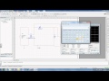
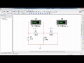
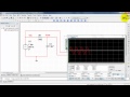
This video describes the basics of using National Instruments MultiSim Circuit Design and Simulation software. The simulation is that of a half wave rectifier with filter capacitor and 3 pin regulator to create a regulated DC current from AC currnet. Thi
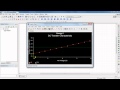
Set up an AC Analysis to plot the frequency response (both magnitude and phase) of a circuit.

Find phasor node voltages with a Single Frequency AC Analysis. The results can be displayed in either rectangular or polar format.
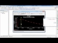
Learn how to plot the behavior of one or more circuit variables due to sweeping a voltage source through a range of values.
Evaluate changes in circuit behavior due to temperature.
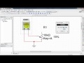
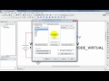
The linear potentiometer can serve as a pair of variable resistors. The resistance can be changed in real time with interative simulation through use of a slider or keypress.
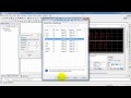
Find node voltages with a DC Operating Point analysis.
Learn how to measure DC current with a voltmeter indicator.
Place and configure the Function Generator, an instrument that produces three basic waveform shapes: sine, triangle, and square.
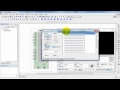
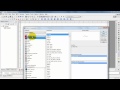
Find some of the more commonly-used circuit components including: resistor, capacitor, inductor, potentiometer, ground, DC voltage source, DC current source and switch.
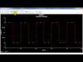
Set up a Transient Analysis to plot time-domain circuit response waveforms.
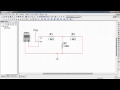
Place a configure the dual power supplies used for circuits based on bipolar junction transistors (BJTs).
Create digital signal sequences with the Word Generator. Also learn how to use ABM (Analog Behavior Model) voltage sources to translate the fixed voltage output of the Word Generator (0.5V and 4.5V) to any required levels.
Learn how to make net names visible and how to rename them.
Learn how to measure the resistance of a resistor network using the Multimeter as an ohmmeter.
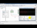
Learn basic operation of the Multisim two-channel oscilloscope to display waveforms.
Place and configure the AC voltage source, a sinusoidal source suitable for interactive simulation, transient analysis, and AC (frequency sweep) analysis.
Learn how to measure DC current with a voltmeter indicator
Distinguish oscilloscope traces by assigning unique colors to the associated signal nets.
Display RMS and average value with a measurement probe.
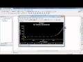
Use a DC Sweep analysis to plot the current-voltage characteristic of a diode; also known as an I-V characteristic, a plot of the diode current as a function of voltage.
Learn how to use Grapher View cursors to find the maximum value of a plot trace.
Use a nested DC Sweep analysis to plot the base characteristic of an NPN bipolar junction transistor (BJT); the base characteristic is base current vs. base-emitter voltage at various levels of collector-emitter voltage.
Use a nested DC Sweep analysis to plot the collector characteristic of an NPN bipolar junction transistor (BJT); the collector characteristic is collector current vs. collector-emitter voltage at various levels of base current.
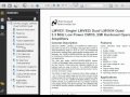
This video shows you how to create a component in Multisim (and import a SPICE model for simulation) by using an existing component as a template.
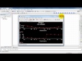
This video will teach you how to use Multisim and the SPICE Netlist Viewer to gain a greater insight into SPICE simulation. Schematic changes are reflected directly within the SPICE Netlist Viewer to give you an insantaneous view of the underworkings of